
| Input | |
| Pressure ranges | 60, 100, 250, 400 and 600 bar |
| Pressure reference | Gauge |
| Over pressure | 2 x rated pressure |
| Burst pressure | 4 x rated pressure |
| Output | |
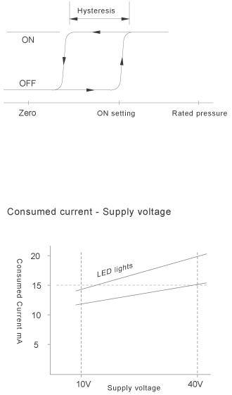
| Pressure setting method | Adjustable by 25 turns trimmer |
| Pressure setting range ( ON setting ) | 0 to 100% of rated pressure |
| Hysteresis range setting ( OFF setting ) | From -1 to -15% of the ON setting |
| Display of pressure ON | Red LED indicator lights |
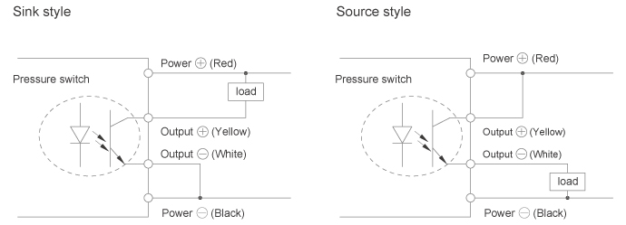
| Output interface | Open collector insulated by a photo-coupler |
| Output capacity | 40Vdc 100 mA |
| Residual voltage | 1 V maximum |
| Repeatability | 0.01% |
| Electrical | |
| Supply voltage | 10 – 40Vdc |
| Reverse polarity | Protected |
| Power requirements | < 14 mA |
| Insulation resistance | 100MΩ 100Vdc |
| Response time | < 1ms |
| Environmental | |
| Operating temperature range | - 20 to 80℃ |
| Storage temperature range | - 40 to 90℃ |
| Vibration tolerance | 10g's to 50Hz |
| Mechanical shock | 15g ( 11mS ) |
| Operating humidity | 95% RH |
| Physical | |
| Pressure media | Stainless steel 17- 4PH |
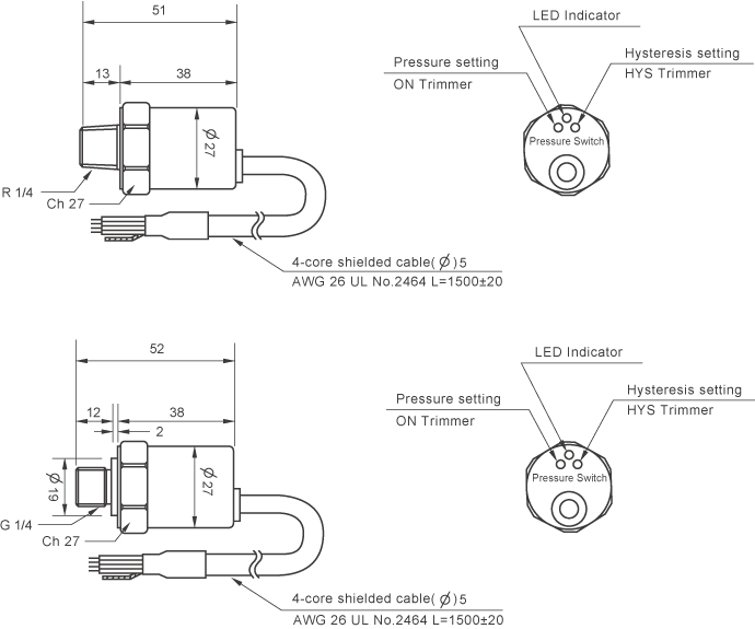
| Pressure connection | G 1/ 4" R 1/ 4" |
| Housing material | Stainless steel 304 |
| Electrical connection | Shielded cable AWG26 UL No.2464 |
| Enclosure rating | IP54 |
| Natural frequency | 20KHz 17-4PH |
| Weight | 120grams approx |
| CE Conformity | EN61326 - 1 ( 2006 ) IEC / EN61000 - 4 - 2 / 3 / 4 / 6 |
Description
The PSW661 Pressure Switch integrate a pressure sensor and an open collector insulated by a
photo-coupler and an electronic circuit are used as an output.
Pressure Switch PSW661 are designed mainly to pressure control and setting in air, oil, water and other liquids in the process. They are also be used in compressor, injection, press and hydraulic power unit.
Technical data
Note: Pressure setting ( ON setting ) and Hysteresis setting ( OFF setting ) trimmers are turned to the maximum in the
clockwise direction after final.
Adjustment
- 1. Pressure setting ( ON Setting )
Apply required pressure to the Pressure Switch and rotate
" Pressure setting trimmer" counter-clockwise until LED indicator lights. - 2. Hysteresis setting ( OFF Setting )
Reduce pressure to obtain the required off pressure and
rotate " Hysteresis setting trimmer." counter-clockwise
until LED indicator goes off. - 3. Check.
Repeat ON and OFF setting at least once to make sure the setting is correct.

Switching operation
Electrical connection
Dimensions : mm
Ordering information

